

 English
 عربى
عربى
Industry News
Content
- 1 Why Rotary Valve Safety Matters in Industrial Operations
- 2 Understanding the Core Safety Risks of Rotary Valves
- 3 Explosion Protection: ATEX, NFPA, and EN Standards
- 4 Proper Installation Practices to Prevent Safety Incidents
- 5 Lockout/Tagout Procedures for Rotary Valve Maintenance
- 6 Routine Inspection and Preventive Maintenance Schedule
- 7 Operator Training and Safety Culture
Why Rotary Valve Safety Matters in Industrial Operations
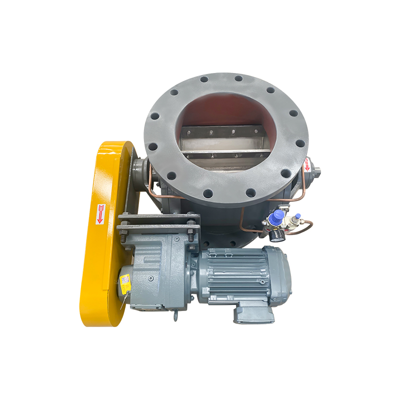
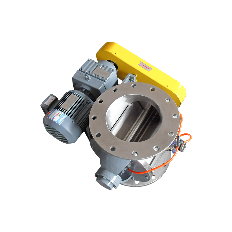
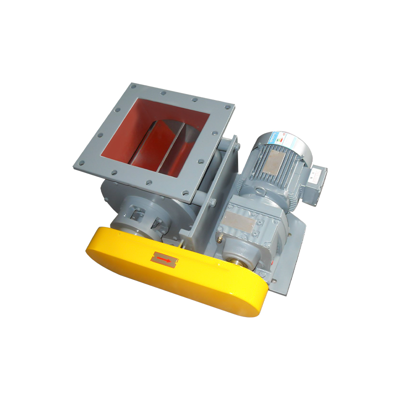
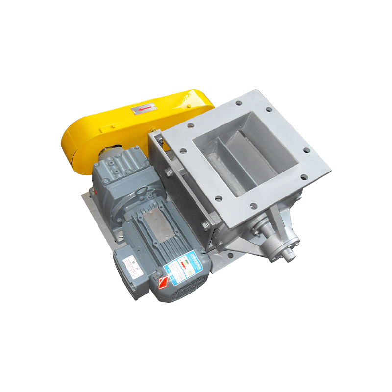
Rotary valves — also known as rotary airlocks, rotary feeders, or star valves — are mechanical devices used to meter, control, and isolate the flow of bulk solids, powders, and granular materials between zones of different pressure. They are found in cement plants, grain handling facilities, plastics manufacturing, food processing lines, pharmaceutical production, and chemical processing units. Despite their relatively simple appearance, rotary valves operate at the intersection of mechanical motion, pressure differentials, and often combustible or hazardous materials. When safety protocols are ignored or equipment is improperly maintained, the consequences can include dust explosions, pressure blowbacks, bearing failures, and serious injury to personnel.
A complete approach to rotary valve safety is not limited to selecting the right valve for the application. It encompasses proper installation, explosion protection compliance, routine inspection, maintenance best practices, and operator training. This guide addresses each of these areas in practical detail so that engineers, maintenance teams, and plant managers can build a reliable safety framework around rotary valve systems.
Understanding the Core Safety Risks of Rotary Valves
Before establishing safety protocols, it is essential to identify the primary hazards associated with rotary valve operation. The most significant risks include:
- Dust explosions: When handling combustible powders such as flour, sugar, coal dust, aluminum powder, or grain, any leak or spark within the rotary valve housing can ignite a suspended dust cloud. The valve is often positioned between a dust collector and a conveying line, making it a potential flame propagation point in an explosion event.
- Pressure blowback: If the rotor tip clearance is too large, or if the valve is undersized for the pressure differential it must seal against, process gas or air can blow back through the valve, disrupting material flow and creating dangerous pressure surges upstream.
- Mechanical entrapment: Maintenance personnel who open the valve housing without proper lockout/tagout (LOTO) procedures face a serious risk of hand or finger injury from the rotating rotor, which may restart unexpectedly if power is not fully isolated.
- Bearing and seal failure: Contamination of bearings by the conveyed material, or inadequate lubrication, leads to overheating and premature failure. In high-temperature applications, failed seals can allow hot gases or flames to migrate through the valve body.
- Foreign object damage: Hard or oversized objects in the material stream can jam between the rotor and housing, causing rotor seizure, motor overload, and structural damage to the valve body.
Explosion Protection: ATEX, NFPA, and EN Standards
For applications involving combustible dusts or flammable gases, rotary valves must comply with the applicable explosion protection standards. In Europe, the ATEX directive (2014/34/EU) requires that equipment used in explosive atmospheres be certified for the appropriate equipment category and zone classification. In North America, NFPA 69 (Standard on Explosion Prevention Systems) and NFPA 654 (Standard for the Prevention of Fire and Dust Explosions) provide the regulatory framework for dust handling systems, including rotary valves used as isolation devices.
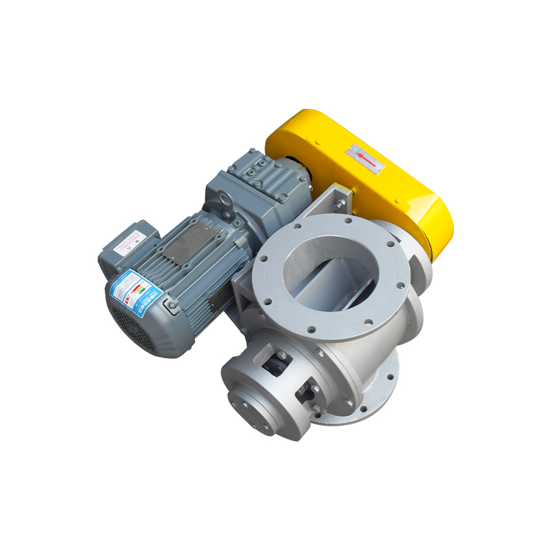
A rotary valve intended for use as an explosion isolation device must demonstrate a certified Maximum Experimental Safe Gap (MESG) containment capability or a certified Kst/Pmax rating compatibility with the material being handled. Not all rotary valves are suitable for explosion isolation service — only those that have been independently tested and certified to EN 16447 or equivalent standards can be used as passive explosion isolation components in a dust explosion protection system.
When specifying a rotary valve for hazardous duty, always request the full ATEX or IECEx certificate, including the equipment group, category, and temperature class. Mismatching equipment classification to zone classification is one of the most common compliance errors in dust handling installations.
Proper Installation Practices to Prevent Safety Incidents
Safe operation begins at installation. A rotary valve that is correctly sized, oriented, and integrated into its surrounding system will perform with far fewer safety-critical failures than one that has been installed incorrectly.
Sizing and Pressure Differential
The valve must be sized to handle the required volumetric throughput at the actual rotor speed (typically between 6 and 30 RPM for most applications) without over-pressurizing the inlet pocket. The pressure differential across the valve — the difference between inlet and outlet pressure — must not exceed the valve's rated differential pressure. Exceeding this rating forces gas to blow back through the rotor pocket, contaminating upstream equipment and creating pressure shock events. Most standard rotary valves are rated for differential pressures up to 0.5 bar (7 psi), while heavy-duty designs can handle up to 1.0 bar (14.5 psi) or more.
Inlet and Outlet Transition Design
The inlet connection should be designed to prevent material bridging or arching above the valve, which can create sudden slug loads when the bridge breaks. A straight vertical drop section of at least 1.5 times the inlet dimension is recommended above the valve inlet. The outlet must allow material to discharge freely without building back-pressure in the rotor pockets. Restricted outlets are a major cause of rotor jamming and housing overpressure.
Grounding and Bonding for Static Electricity
When handling combustible or flammable materials, the valve housing, drive assembly, and connected ductwork must be electrically grounded and bonded to prevent static charge buildup. Electrostatic discharge within a dust-laden atmosphere can serve as an ignition source. Resistance to ground should not exceed 10 ohms per IEC 60079-32-1 guidance for equipment handling flammable materials.
Lockout/Tagout Procedures for Rotary Valve Maintenance
All maintenance activities on rotary valves — including rotor removal, seal replacement, bearing inspection, and housing cleaning — must be conducted under a formal lockout/tagout (LOTO) procedure compliant with OSHA 29 CFR 1910.147 (Control of Hazardous Energy) or equivalent national regulations. The procedure must isolate all energy sources, including:
- Electrical power to the drive motor and any associated controls or interlocks
- Pneumatic or hydraulic pressure in any actuated components connected to the valve
- Process pressure in the upstream and downstream conveying lines, which must be depressurized before opening the housing
- Gravity energy — stored material above the valve must be blocked or diverted so it cannot fall into the open housing during maintenance
A dedicated LOTO procedure card should be posted at the valve location and reviewed with maintenance personnel before every service event. Group lockout practices, where multiple technicians each apply their own personal lock, are strongly recommended when more than one person is working on the same equipment.
Routine Inspection and Preventive Maintenance Schedule
A consistent preventive maintenance program is the foundation of long-term rotary valve safety. The following table outlines a practical inspection and maintenance schedule based on industry best practices:
| Frequency | Inspection / Maintenance Task |
| Daily | Check for unusual noise, vibration, or overheating; verify motor amperage is within normal range |
| Weekly | Inspect shaft seals for leakage; check gearbox oil level; verify grounding continuity |
| Monthly | Lubricate bearings per manufacturer specifications; inspect rotor tip clearance if access permits |
| Quarterly | Open housing for internal inspection; measure rotor tip-to-housing clearance; replace worn end plates or seals |
| Annually | Full strip-down inspection; replace bearings; verify ATEX certification integrity; update LOTO procedure if hardware has changed |
Rotor tip clearance is one of the most critical measurements in rotary valve maintenance. Standard clearances typically range from 0.1 mm to 0.4 mm (0.004" to 0.016") depending on the valve size and material handled. Clearances beyond the manufacturer's maximum tolerance allow excessive gas bypass, reduce sealing performance, and, in explosion-rated applications, may invalidate the valve's isolation certification.
Operator Training and Safety Culture
Technical safeguards and maintenance schedules are only as effective as the people implementing them. Operators who interact with rotary valve systems on a daily basis must understand not just the normal operating parameters, but also the early warning signs of developing faults — unusual motor current draw, changes in discharge rate, abnormal noise from the gearbox, or visible dust leakage from shaft seals. Early identification of these symptoms allows corrective action before a minor issue becomes a safety event.
Training programs should cover the specific hazard profile of the materials being handled, the applicable explosion protection zone classification of the installation area, emergency shutdown procedures, and the facility's LOTO program. Refresher training should be conducted at least annually, and any time a significant change is made to the process or equipment configuration. Documenting all training, inspections, and maintenance activities creates a traceable safety record that supports regulatory compliance and root cause analysis in the event of an incident.