

 English
 عربى
عربى
Industry News
Content
- 1 Fundamental Working Principles of Rotary Valves
- 2 Major Types of Rotary Valve Designs
- 3 Large-Size Rotary Valve Characteristics and Applications
- 4 Specialized Rotary Valve Variations
- 5 Materials of Construction and Component Selection
- 6 Drive Systems and Speed Control
- 7 Sealing Systems and Airlock Performance
- 8 Maintenance Requirements and Service Life
- 9 Application Selection Criteria
- 10 Integration with Material Handling Systems
Rotary valves, also known as rotary airlocks or rotary feeders, are essential mechanical devices used extensively in material handling systems across diverse industries. These specialized components serve dual functions as both metering devices and airlock systems, controlling the flow of bulk materials while maintaining pressure differentials between different processing zones. From food processing plants and pharmaceutical manufacturing to chemical production and power generation facilities, rotary valves enable precise material transfer in pneumatic conveying systems, dust collection networks, and gravity-fed applications. Understanding the fundamental working principles, various design types, and specific applications of rotary valves—particularly large-size configurations—is crucial for engineers, plant managers, and maintenance professionals responsible for optimizing material handling operations.
Fundamental Working Principles of Rotary Valves
The operating principle of rotary valves centers on a multi-vaned rotor housed within a cylindrical or specially shaped casing. As the rotor turns, individual pockets formed between adjacent vanes receive material from an inlet opening positioned at the top of the valve housing. The rotation carries this material through an arc until it reaches the discharge opening at the bottom, where the product exits into downstream equipment or conveying systems. This continuous rotation creates a sequential filling and emptying cycle that maintains steady material flow while the rotor body itself acts as a physical barrier preventing direct air passage between inlet and outlet connections.
The airlock functionality results from the close tolerances maintained between rotor components and the housing. As each pocket rotates through the transfer cycle, the rotor tips create sliding seals against the housing interior, while the rotor ends seal against stationary end plates. These clearances, typically measured in thousandths of an inch, allow some air leakage but provide sufficient restriction to maintain pressure differentials necessary for pneumatic conveying or dust collection systems. The effectiveness of this sealing depends on manufacturing precision, material selection, and proper maintenance of clearances throughout the valve's operational life.
Material Flow Mechanics
Material enters the rotary valve under gravity flow from overhead hoppers or bins, filling the rotor pockets as they pass beneath the inlet opening. The volume of material each pocket can accommodate depends on pocket geometry, rotor diameter, and rotor width. As rotation continues, the filled pocket travels away from the inlet zone while remaining sealed from both inlet and outlet until it reaches the discharge position. At discharge, the pocket opens to the outlet connection, allowing material to exit by gravity or conveying air assistance. The discharge rate can be controlled precisely by adjusting rotor speed, making rotary valves effective metering devices for processes requiring consistent feed rates.
Major Types of Rotary Valve Designs
Rotary valves are manufactured in several distinct design configurations, each optimized for specific material characteristics, operating conditions, and performance requirements. The closed-end rotor design features solid end discs that completely seal the pocket ends, preventing material and air from escaping axially. This configuration provides superior airlock performance and is preferred for fine powders, pneumatic conveying applications, and situations requiring minimal air leakage. The contained pocket geometry also prevents material from working into bearing areas, reducing contamination risks and extending bearing life in dusty environments.
Open-end rotor designs eliminate the end discs, allowing material to contact the housing end plates directly. While this configuration provides less effective air sealing than closed-end rotors, it offers advantages for free-flowing granular materials that discharge more readily without end restrictions. Open-end rotors also simplify cleaning and maintenance access, making them popular in food processing and pharmaceutical applications requiring frequent sanitation. The reduced pocket restriction helps prevent bridging of materials with poor flow characteristics, though at the cost of some airlock effectiveness and potential for material leakage past end plate clearances.
Pocket Configuration Variations
The geometry of rotor pockets significantly influences valve performance with different materials. Round pocket rotors, featuring curved vane profiles, provide smooth material handling with minimal product degradation, making them suitable for fragile materials like cereal flakes or pharmaceutical tablets. Square pocket designs maximize volumetric capacity for a given rotor diameter, increasing throughput while providing positive displacement that helps move sticky or cohesive materials. Beveled pocket rotors incorporate angled vane edges that facilitate discharge and reduce material hang-up, particularly beneficial when handling materials prone to bridging or with irregular particle shapes.
| Rotor Type | Best Applications | Key Advantage | Limitation |
| Closed-End Round Pocket | Fine powders, pneumatic systems | Excellent airlock performance | Moderate capacity |
| Open-End Square Pocket | Granular materials, high capacity | Maximum throughput | Higher air leakage |
| Adjustable Blade | Variable materials, flexible service | Clearance adjustment capability | Mechanical complexity |
| Drop-Through | Fragile products, gentle handling | Minimal product damage | Poor airlock performance |
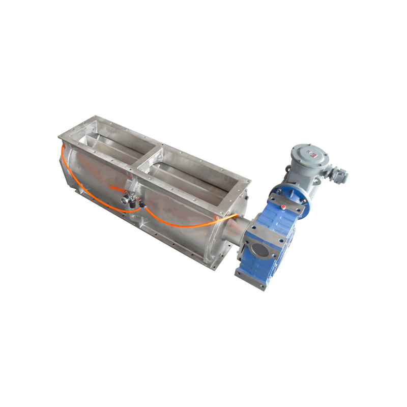
Large-Size Rotary Valve Characteristics and Applications
Large-size rotary valves, typically defined as units with rotor diameters exceeding 18 inches (450mm), address material handling requirements in high-capacity industrial processes. These substantial units can achieve throughput rates ranging from tens to hundreds of tons per hour depending on material characteristics, rotor dimensions, and operating speeds. Common applications include coal handling in power generation facilities, grain processing in agricultural operations, polymer pellet conveying in plastics manufacturing, and bulk chemical processing where massive material volumes must be transferred reliably while maintaining process control.
The engineering challenges in large-size rotary valves differ significantly from smaller units. The increased rotor diameter creates greater peripheral speeds even at moderate rotational velocities, potentially causing excessive wear rates or material degradation. Bearing loads increase substantially with rotor size and weight, requiring heavy-duty bearing systems and robust shaft designs to prevent deflection that could cause rotor-to-housing contact. Drive systems must provide adequate torque to overcome material resistance and friction forces while maintaining precise speed control for accurate metering. Thermal expansion effects become more pronounced in large valves, necessitating careful clearance management to prevent binding during temperature changes while maintaining effective sealing.
Structural Considerations for Large Valves
Large rotary valves require substantial structural support to accommodate their weight and the forces generated during operation. Housing fabrication typically employs heavy-wall steel plate construction rather than castings, providing necessary strength while allowing custom sizing. Reinforcing ribs and structural members prevent housing distortion under internal pressure or external loads from connecting ductwork. Mounting arrangements must distribute the valve's weight—which can exceed several thousand pounds for the largest units—to facility structures capable of supporting these loads without deflection that could affect valve alignment or performance.
Specialized Rotary Valve Variations
Beyond standard configurations, specialized rotary valve designs address unique application challenges. Blow-through rotary valves incorporate air injection ports that introduce pneumatic conveying air directly into rotor pockets as they approach the discharge position, accelerating material into downstream conveying lines. This design improves material pickup in dense-phase conveying systems and reduces the rotor power required to push material into pressurized conveying lines. However, the air injection increases overall system air consumption and may not be suitable for materials sensitive to air exposure or applications requiring minimal dust generation.
Drop-through or low-shear rotary valves feature enlarged clearances and simplified rotor geometries that minimize mechanical forces on materials passing through the valve. These designs sacrifice airlock performance to preserve product integrity, making them ideal for fragile materials like breakfast cereals, expanded snack foods, or delicate pharmaceutical products where particle breakage must be minimized. The reduced sealing effectiveness limits their use to low-pressure applications or situations where some air leakage is acceptable. Double-dump or segmented discharge valves provide enhanced airlock performance by incorporating intermediate sealing chambers that prevent direct air passage between inlet and outlet even when individual pockets are simultaneously exposed to both zones.
Materials of Construction and Component Selection
Rotary valve components must be constructed from materials compatible with the handled product and operating environment. Carbon steel construction suits most industrial applications handling non-corrosive materials at moderate temperatures, providing adequate strength and wear resistance at economical cost. Stainless steel construction, typically Type 304 or 316, is mandatory for food, pharmaceutical, and chemical applications requiring corrosion resistance or product purity. Stainless construction also facilitates cleaning and sanitation in applications subject to hygiene regulations or frequent product changeovers.
Abrasive materials demand specialized wear-resistant components to achieve acceptable service life. Rotor tips may be manufactured from tool steel, hardened to 60+ Rockwell C, or fitted with replaceable wear strips of stellite, tungsten carbide, or ceramic materials. Housing wear areas can be protected with replaceable liners of abrasion-resistant materials, allowing economical refurbishment when wear occurs rather than replacing entire housings. For extreme abrasion service, complete valve construction from hardened materials or exotic alloys may be justified despite significant cost premiums. High-temperature applications require materials maintaining strength and dimensional stability at elevated temperatures, including heat-resistant alloys and specialized sealing arrangements accommodating thermal expansion.
Drive Systems and Speed Control
Rotary valve drive systems must provide reliable power transmission while enabling precise speed control for accurate material metering. Direct-drive arrangements couple the motor shaft directly to the valve shaft through flexible couplings, offering simplicity and compact installation but limiting speed adjustment options to motor speed variation. Chain or belt drive systems provide speed reduction through sprockets or sheaves, allowing standard motor speeds to drive valves at appropriate rotational velocities. These indirect drives also provide some overload protection through slippage or shear pin mechanisms that prevent valve damage if rotor jamming occurs.
Variable frequency drives (VFDs) have become standard for rotary valve speed control, enabling precise adjustment of feed rates to match process demands. VFD systems allow remote speed control through process automation systems, supporting integration into sophisticated material handling networks requiring dynamic feed rate adjustment. The electronic motor control also provides soft-starting that reduces mechanical stress during startup and enables torque monitoring that can detect rotor loading changes indicating material flow problems or component wear. For critical applications, redundant drive systems or quick-change drive components minimize downtime if drive system failures occur.
Sealing Systems and Airlock Performance
The effectiveness of rotary valves as airlocks depends critically on sealing system design and maintenance. Rotor tip seals create the primary barrier preventing air passage between valve inlet and outlet. These seals may be integral machined surfaces on metal rotors, replaceable elastomeric or composite strips attached to rotor blades, or adjustable mechanical seals that can be tightened to compensate for wear. The seal design must balance airlock effectiveness against wear rate and power consumption—tighter seals reduce air leakage but increase friction, heat generation, and component wear.
End plate sealing prevents axial air leakage between rotor ends and housing end covers. Static gaskets seal the joint between housing and end plates, while dynamic clearances between rotating rotor ends and stationary end plates must be minimized without creating excessive friction or binding. Some designs incorporate adjustable end plates that can be repositioned to compensate for wear or thermal expansion, maintaining optimal clearances throughout the valve's service life. Shaft seals prevent air and material leakage at points where the drive shaft penetrates the housing, using combinations of lip seals, mechanical seals, or packing glands depending on pressure, temperature, and cleanliness requirements.
Maintenance Requirements and Service Life
Proper maintenance is essential for achieving acceptable rotary valve service life and performance. Routine inspection programs should monitor rotor tip clearances, bearing condition, and seal integrity to detect wear before it causes operational problems or catastrophic failures. Bearing lubrication following manufacturer specifications prevents premature bearing failure, while periodic alignment checks ensure the rotor remains centered within the housing without excessive runout. Inspection of mounting bolts, coupling components, and drive system elements should be performed according to maintenance schedules appropriate for operating severity and criticality.
- Monitor rotor tip clearances monthly in abrasive service, quarterly in moderate service
- Inspect bearings for temperature, vibration, and noise indicating developing problems
- Check drive belt or chain tension and wear, replacing before failure occurs
- Verify motor current draw to detect increases indicating rotor drag or bearing problems
- Clean internal surfaces during shutdowns to prevent material buildup affecting performance
- Document wear rates to predict component replacement timing and optimize spare parts inventory
Application Selection Criteria
Selecting appropriate rotary valve configurations requires comprehensive evaluation of material characteristics, system requirements, and operational conditions. Material properties including particle size distribution, bulk density, flowability, abrasiveness, temperature, and moisture content all influence optimal valve design. Free-flowing materials with low bulk density suit open-end rotors with large pockets, while cohesive or sticky materials may require closed-end designs with positive displacement characteristics. Abrasive materials necessitate hardened components and potentially oversized valves operating at reduced speeds to minimize wear rates.
System pressure differentials determine required airlock performance and influence rotor design selection. Low-pressure applications below 5 psi differential allow simpler, more economical valve configurations, while higher pressures demand enhanced sealing arrangements and robust construction. The required throughput capacity establishes minimum rotor dimensions and operating speeds, with larger rotors or higher speeds needed for greater material volumes. Installation constraints including available space, mounting orientation, and accessibility for maintenance may favor certain valve types over alternatives with equivalent performance capabilities.
Integration with Material Handling Systems
Successful rotary valve operation depends on proper integration within the broader material handling system. Upstream equipment must provide consistent material flow to the valve inlet, with properly designed hoppers preventing bridging or ratholing that could cause erratic feeding. Hopper outlet dimensions should match or slightly exceed valve inlet size to ensure complete pocket filling, while hopper angles must exceed the material's angle of repose to promote gravity flow. Vent connections on the valve housing allow displacement of air from filling pockets and admission of air to discharging pockets, preventing pressure buildup or vacuum formation that could affect material flow.
Downstream equipment must accommodate the material discharge characteristics of the rotary valve. For gravity discharge into hoppers or vessels, adequate clearance beneath the valve outlet prevents material backup that could jam the rotor. In pneumatic conveying applications, the conveying line pickup velocity must be sufficient to transport discharged material away from the valve without accumulation. Proper coordination between rotary valve feed rate and conveying system capacity prevents either material accumulation causing valve burial or insufficient material loading resulting in inefficient conveying. System controls should interlock the rotary valve with upstream and downstream equipment, shutting down the valve if material flow disruptions occur to prevent equipment damage or safety hazards.
Rotary valves represent sophisticated yet reliable material handling devices that have become indispensable across countless industrial processes. From their fundamental working principles based on rotating pockets creating controlled material flow and pressure separation, through diverse design types optimized for specific applications, to the specialized engineering required for large-size installations, these versatile components enable efficient bulk material handling. Understanding the mechanical principles, design variations, and application considerations for rotary valves—particularly large-capacity units—empowers engineers and operators to select, install, and maintain these critical components for optimal performance, longevity, and return on investment in material handling operations.


