

 English
 عربى
عربى
Industry News
Content
- 1 What Rotary Airlock Valves Do and Why Design Matters
- 2 Square Port Rotary Valves: Design and Core Advantages
- 3 Round Port Rotary Valves: When Circular Geometry Wins
- 4 Drop-Through Rotary Airlock Valves
- 5 Blow-Through Rotary Airlock Valves
- 6 Side Entry Rotary Valves and Specialty Configurations
- 7 Comparing Rotary Airlock Valve Types Side by Side
- 8 Material of Construction and Its Effect on Performance
- 9 Selecting the Right Rotary Airlock for Your System
What Rotary Airlock Valves Do and Why Design Matters
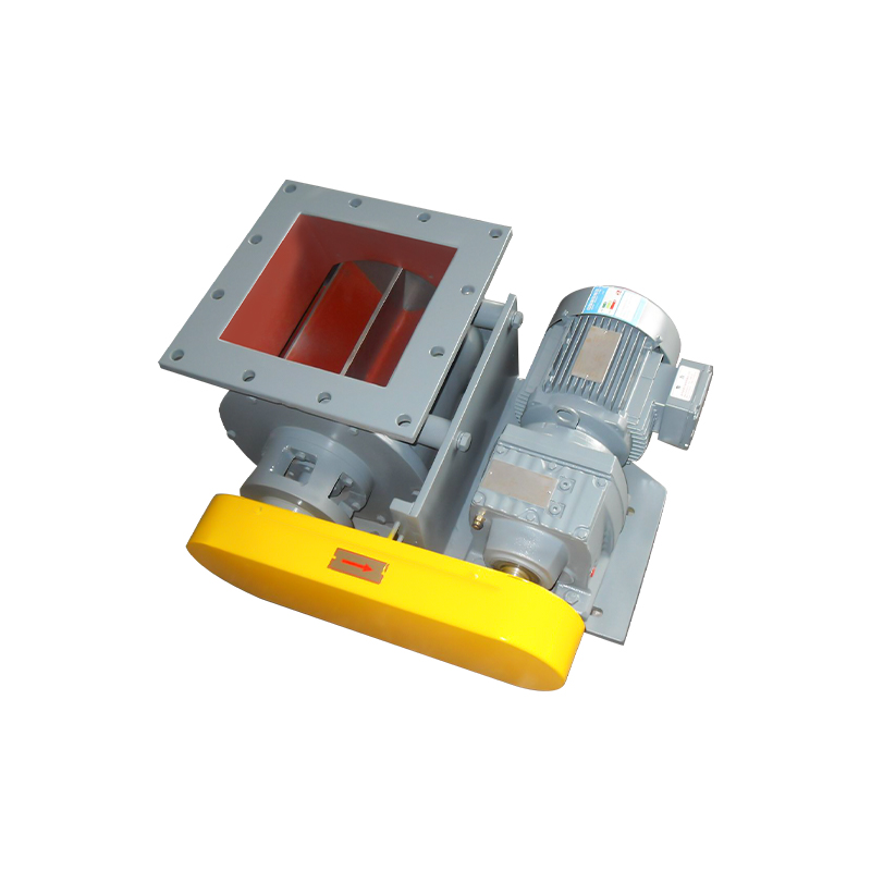
Rotary airlock valves — also called rotary feeders or rotary airlocks — are mechanical devices installed at the discharge point of hoppers, silos, cyclones, bag filters, and pneumatic conveying systems. Their primary function is to meter bulk solid materials from one pressure zone into another while maintaining a consistent pressure differential between the two zones. Without an effective airlock, air leakage compromises conveying efficiency, causes material backflow, and can introduce safety hazards in dust-handling environments.
The internal geometry of a rotary airlock valve — specifically the shape of its inlet and outlet ports — has a direct and measurable impact on how well it performs in any given application. Square port rotary valves, round port valves, drop-through configurations, and blow-through designs each have distinct strengths and weaknesses. Selecting the wrong type leads to premature wear, inconsistent material flow, excessive air leakage, or product degradation. Understanding these differences in practical terms is what separates a well-engineered bulk handling system from one that causes constant operational headaches.
Square Port Rotary Valves: Design and Core Advantages
Square port rotary valves feature an inlet and outlet opening that is square or rectangular in cross-section rather than circular. This geometric choice is not arbitrary — it is driven by the need to maximize the open area of the port relative to the rotor pocket volume. A square port covers more of the rotor's pocket opening at any given moment compared to a round port of equivalent nominal size, which means more material can enter and exit each pocket per revolution without restriction.
The practical consequence of this larger open area is improved volumetric efficiency. Square port valves are particularly well-suited to handling light, fluffy, or low-bulk-density materials — such as flour, starch, powdered chemicals, carbon black, or fine wood dust — that require generous port openings to feed consistently without bridging or flooding. The geometry also reduces the shear forces applied to fragile or pelletized materials as they pass through the valve, since the rotor blades don't clip as large a portion of the material stream during rotation.
Key Benefits of Square Port Design
- Higher volumetric efficiency due to maximized open port area relative to rotor size
- Reduced particle attrition, making them suitable for fragile or pelletized materials
- Better performance with low-density, aerated, or fluffy bulk solids
- Improved consistency of material metering when handling fine powders
- Widely compatible with standard hopper and silo outlet configurations
Limitations to Consider
- The square housing geometry can make cleaning and inspection more difficult than round port designs
- Corners in the housing can accumulate residual material in sanitary or food-grade applications
- Less structurally rigid than round housings under very high differential pressures
- May require more precise rotor-to-housing clearances to maintain air seal effectiveness
Round Port Rotary Valves: When Circular Geometry Wins
Round port rotary valves use a circular inlet and outlet opening. The circular cross-section means the port area is inherently smaller relative to the rotor diameter compared to a square port of the same nominal size. However, this geometry offers its own set of advantages that make it the preferred choice in certain applications. The circular housing is mechanically stronger under pressure, easier to manufacture to tight tolerances, and simpler to clean — particularly in sanitary applications where product residue in corners poses contamination risks.
Round port valves handle dense, coarse, or granular materials particularly well. Grains, pellets, granulated plastics, and similar products flow reliably through the circular opening without the bridging concerns that sometimes affect fine powders. The reduced port area also means slightly better air sealing in some configurations, since there is less open area for air to bypass during rotor rotation. In high differential pressure applications — such as pressure pneumatic conveying systems operating above 10 PSI — the structural integrity of a round housing can be a decisive advantage.
Drop-Through Rotary Airlock Valves
Drop-through rotary airlocks are the most common configuration in bulk material handling. In this design, material falls vertically through the valve body — entering at the top inlet, filling the rotor pockets, and discharging through the bottom outlet by gravity. The rotor rotates continuously, cycling each pocket from the inlet zone to the outlet zone and back. Drop-through valves are simple, robust, and applicable across a wide range of materials and industries.
Both square port and round port designs are available in drop-through configurations. The choice between them at this configuration level comes down to the material characteristics and the specific requirements of the system. Drop-through valves with square ports are generally preferred for fine powders and low-density materials, while round port drop-through valves are more common in coarser material handling. The drop-through design is also the easiest to maintain — most models allow the rotor to be removed radially without disconnecting the valve body from the pipeline, which significantly reduces downtime during cleaning or blade replacement.
Drop-Through Valve Strengths
- Gravity-assisted flow reduces the risk of material bridging inside the valve
- Simple construction with fewer specialized components than blow-through designs
- Easier rotor removal for maintenance without full system shutdown
- Suitable for most standard pneumatic conveying and gravity discharge systems
Blow-Through Rotary Airlock Valves
Blow-through rotary airlock valves differ fundamentally in how material exits the valve. Instead of relying on gravity to discharge material downward through the bottom of the housing, blow-through valves route the conveying air stream directly through the bottom of the valve body. The air passes through the rotor pockets and carries material horizontally into the conveying pipeline. This makes blow-through valves ideal for situations where the conveying line runs horizontally or where the material being handled is so light or sticky that gravity discharge is unreliable.
Blow-through designs are particularly effective with extremely fine powders, sticky or cohesive materials, and any product prone to flooding. Because the conveying air sweeps each rotor pocket clean as it rotates through the discharge zone, material carryover and pocket buildup are minimized. However, blow-through valves have higher air leakage rates than drop-through designs due to the direct air pathway through the rotor, and they require more careful engineering of the conveying system to account for this. They are also more expensive and mechanically complex, with end plates that must maintain precise clearances against the rotor faces under the pressure of the conveying air stream.
Side Entry Rotary Valves and Specialty Configurations
Side entry rotary valves are designed for applications where the material feed comes in from the side rather than from above. This configuration is common in installations where head space above the valve is severely limited, or where the upstream equipment — such as a screw conveyor or drag chain conveyor — discharges horizontally. Side entry valves are less common than drop-through designs and require careful consideration of the material's flow characteristics, since gravity is no longer assisting the filling of rotor pockets.
Specialty configurations also include valves with adjustable tip clearances, high-temperature versions with ceramic rotors or stainless steel housings rated for service above 300°C, and explosion-proof designs for use in potentially explosive dust environments classified under ATEX or NEC standards. For abrasive materials such as sand, mineral powders, or recycled glass, hardened rotor blades — often made from AR400 steel, ceramic-lined, or carbide-coated — are available to extend service life significantly beyond what a standard mild steel rotor would achieve.
Comparing Rotary Airlock Valve Types Side by Side
| Valve Type | Best Material Type | Air Seal Quality | Maintenance Ease | Relative Cost |
| Square Port Drop-Through | Fine powders, low density | Good | High | Moderate |
| Round Port Drop-Through | Granules, coarse solids | Very Good | High | Moderate |
| Blow-Through | Sticky, ultra-fine powders | Moderate | Moderate | High |
| Side Entry | Horizontal feed applications | Good | Moderate | Moderate–High |
Material of Construction and Its Effect on Performance
The materials used to manufacture a rotary airlock valve — particularly the housing, rotor, and rotor tip blades — directly affect its durability, sanitary compliance, and suitability for specific service conditions. Standard industrial valves use cast iron housings with mild steel rotors, which are adequate for non-corrosive, non-abrasive applications at ambient temperatures. However, this combination fails quickly when exposed to moisture, corrosive chemicals, or abrasive minerals.
Stainless steel construction — typically 304 or 316 SS — is required for food, pharmaceutical, and chemical applications where hygiene, corrosion resistance, and cleanability are essential. Square port rotary valves in stainless steel are widely specified in food processing facilities handling flour, sugar, starch, and powdered dairy products. For abrasive service, hardened steel or ceramic-tipped rotor blades significantly extend operational life and reduce the frequency of tip clearance adjustment, which is one of the most common maintenance tasks on any rotary airlock valve.
Selecting the Right Rotary Airlock for Your System
Choosing the correct rotary airlock valve requires a systematic evaluation of the material being handled, the operating pressure differential, the required throughput, and the physical constraints of the installation. No single valve type is universally superior — each design represents a set of engineering trade-offs that are more or less favorable depending on the specific application context.
For systems handling fine, low-density powders where consistent metering and low particle attrition are priorities, square port drop-through valves deliver the best balance of performance and maintainability. For dense or granular materials in high-pressure conveying systems, round port valves offer better structural integrity and air sealing. When the material is sticky or the conveying line runs horizontally, a blow-through valve becomes the practical necessity despite its higher cost and greater air leakage. Side entry configurations address installation geometry constraints that no other design can accommodate.
Beyond the port shape and flow configuration, always specify the correct rotor tip clearance for your material — typically 0.1mm to 0.4mm depending on particle size and system pressure — and ensure the drive motor is correctly sized for the starting torque required with the material in the pockets. Consult manufacturer sizing charts and, when in doubt, request an application review from the valve supplier before finalizing the specification. A correctly specified and properly maintained rotary airlock valve will provide years of reliable service; an incorrectly specified one will be a persistent source of production problems from day one.


