

 English
 عربى
عربى
Home / News / Industry News / How Do Rotary Valves Work and Which Type Is Right for Your Application?
Industry News
Content
Rotary valves — also commonly referred to as rotating valves — are a broad category of flow control devices in which the primary mechanism for regulating, directing, or shutting off the flow of a fluid, gas, or bulk solid material is the rotation of an internal element around a fixed axis. Unlike linear motion valves such as gate valves or globe valves, where a stem and disc move in a straight line to open or close the flow path, rotary valves achieve their function through a quarter-turn or multi-turn rotational movement. This fundamental design difference gives rotary valves several practical advantages: they are compact, operate quickly, require lower actuation torque in many configurations, and achieve tight shutoff with minimal wear when properly specified.
Rotary valves are found across virtually every sector of industrial manufacturing and processing — from oil and gas pipelines and chemical reactors to food processing lines, pharmaceutical manufacturing, HVAC systems, and pneumatic conveying installations. Their versatility stems from the wide variety of internal rotating element designs, each engineered to address specific flow characteristics, pressure and temperature conditions, abrasion resistance requirements, and hygiene standards. Understanding how rotating valves function at a mechanical level, and what distinguishes one type from another, is essential for engineers, procurement professionals, and maintenance teams making valve selection and replacement decisions.
The operating principle of all rotary valves rests on the same foundational concept: a rotating element positioned within a valve body controls the passage of flow by aligning or misaligning an opening in the rotating component with the inlet and outlet ports of the body. When the opening in the rotating element aligns with both ports, flow passes through freely. When the element is rotated so that its solid section blocks the ports, flow is shut off. Partial rotation between these two extremes provides throttling — a controlled reduction in flow rate.
The rotating element is connected to an external shaft that passes through the valve body via a sealed stem arrangement. This shaft is turned either manually through a handwheel or lever, or automatically via an electric, pneumatic, or hydraulic actuator. Quarter-turn rotary valves — which achieve full open to full closed in a 90-degree rotation — are the most common configuration because they offer fast operation, simple actuator design, and a clear visual indication of valve position from the external handle orientation. Multi-turn rotary valves, such as certain plug valve designs, complete their operating cycle over multiple full revolutions but offer finer flow control in some applications.
The sealing between the rotating element and the valve body is a critical engineering challenge in rotary valve design. Depending on the application, seals may be achieved through metal-to-metal contact with precisely machined mating surfaces, elastomeric or PTFE seat rings that the rotating element presses against, or in bulk solids applications, close radial clearances between the rotor and housing that minimize leakage of air or product between the high-pressure and low-pressure zones.
The rotary valve family encompasses several distinct valve types, each with a different rotating element geometry and sealing arrangement. Selecting the correct type requires matching the valve's design characteristics to the specific demands of the application — fluid type, pressure class, temperature range, required flow characteristics, and maintenance accessibility.
The ball valve is the most prevalent type of rotary valve in industrial fluid systems. Its rotating element is a sphere — the ball — with a cylindrical bore through its center. When the bore aligns with the pipeline, flow passes through with minimal restriction. A quarter-turn rotation brings the solid side of the ball against the seats, blocking flow completely. Full-bore ball valves have a bore diameter equal to the pipe inner diameter, producing virtually zero pressure drop when fully open — a significant advantage in systems where pressure conservation matters. Reduced-bore designs use a smaller bore for cost savings and are acceptable where some pressure drop is tolerable. Ball valves offer excellent bi-directional shutoff, fast operation, low torque requirements, and are available in a wide range of materials and pressure classes, making them the default choice for isolation duty in most liquid and gas services.
The butterfly valve uses a disc — the "butterfly" — mounted on a central shaft that runs diametrically across the flow bore. When the disc is rotated to be parallel with the flow direction, the valve is fully open. A quarter-turn brings the disc perpendicular to the flow, closing the valve. Because the disc always remains in the flow path even when open, butterfly valves inherently produce more flow resistance than full-bore ball valves, but their compact, lightweight design and low cost relative to body size make them exceptionally popular for large-diameter pipelines — particularly in water treatment, HVAC, and low-pressure process systems. High-performance butterfly valves with eccentric disc geometry (double-offset and triple-offset designs) achieve tight metal-to-metal shutoff suitable for demanding industrial applications at elevated pressures and temperatures.
Plug valves use a cylindrical or tapered plug as the rotating element, with a through-port that aligns with the flow path when open. The plug rotates within the valve body — traditionally lubricated by grease injected under pressure to reduce friction and maintain the seal between the plug and the body bore. Modern plug valves often use PTFE-sleeved or elastomer-lined body designs that eliminate the need for lubrication and provide reliable sealing without the maintenance demands of traditional greased plug valves. Plug valves excel in slurry and dirty fluid services because the rotating motion of the plug tends to sweep the seating surfaces clean during each operation. Multi-port plug valve configurations — with three or four flow ports — allow a single valve to direct flow between multiple pipeline branches, replacing what would otherwise require several separate valves and fittings.
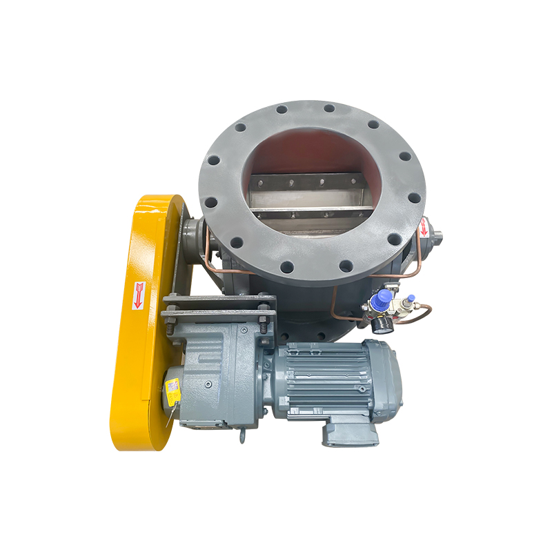
Rotary airlock valves — also called rotary feeders or cellular wheel airlocks — are a specialized category of rotating valve designed specifically for handling bulk solid materials such as powders, granules, pellets, and fibrous materials in pneumatic conveying, dust collection, and storage/discharge systems. Unlike fluid control valves, rotary airlocks do not control the flow of a gas or liquid directly. Instead, they meter bulk solids from a higher-pressure zone (such as a storage hopper or cyclone separator) into a lower-pressure conveying line while maintaining an effective air seal between the two pressure environments. The rotating element is a multi-vaned rotor — typically with 6 to 12 vanes — that turns slowly within a close-tolerance housing. As each cell (pocket between adjacent vanes) passes under the inlet, it fills with material from the hopper above. As the rotor continues to turn, the filled cell moves to the outlet port, where the material discharges into the conveying line below. The close clearance between the rotor vane tips and the housing body minimizes air leakage between zones.
Rotary diverter valves are used to redirect flow from a single inlet to one of two or more outlets — or to combine flows from multiple inlets into a single outlet. They are widely used in pneumatic conveying systems, food and pharmaceutical processing, and blending operations. The rotating element is typically a diverter flap or a rotating tube that swings between outlet positions. In sanitary applications, rotary diverter valves are designed for complete cleanability — with smooth internal surfaces, minimal dead zones, and easy disassembly — to comply with food safety and pharmaceutical GMP standards.
Selecting the most appropriate rotary valve type requires evaluating multiple application parameters simultaneously. The table below provides a structured comparison to support initial selection decisions:
| Valve Type | Best For | Pressure Range | Flow Resistance | Throttling Capability |
| Ball Valve | Clean liquids and gases, isolation duty | Low to very high | Very low (full bore) | Limited (V-port for control) |
| Butterfly Valve | Large diameter pipelines, water, HVAC | Low to medium | Moderate | Good |
| Plug Valve | Slurries, dirty fluids, multi-port routing | Low to high | Low to moderate | Limited |
| Rotary Airlock | Bulk solids metering and air sealing | Low differential pressure | N/A (solids only) | Via speed control |
| Diverter Valve | Flow routing between multiple destinations | Low to medium | Low | Not applicable |
Regardless of specific type, most rotary valves share a common set of structural components. Understanding what each component does helps maintenance teams identify failure points and make informed decisions about repair versus replacement.
Making the correct rotary valve selection requires a systematic evaluation of the operating conditions and functional requirements for each specific application. Rushing this process or relying solely on historical precedent leads to premature valve failure, unplanned maintenance shutdowns, and in critical services, safety incidents. The following factors should be addressed in every valve selection exercise:
Rotary valves are generally recognized as lower-maintenance than linear motion valves because their quarter-turn operation produces less wear on seating surfaces per cycle than the sliding contact of gate or globe valves. However, neglecting preventive maintenance will accelerate seat wear, increase stem leakage, and ultimately result in valve failure at the worst possible moment. Establishing a structured maintenance program based on actual operating cycle frequency and process conditions is the most effective way to maximize rotary valve service life and reliability.
For fluid service ball and butterfly valves, routine maintenance tasks include inspecting and adjusting stem packing compression to prevent external leakage, verifying actuator operation and limit switch calibration, and checking for any signs of seat leakage past the closed valve during planned shutdowns. For rotary airlock valves in bulk solids service, the most critical maintenance tasks are monitoring rotor-to-housing clearances (which increase as the rotor vanes and housing bore wear from abrasive material contact), inspecting end plate seals, and lubricating rotor shaft bearings according to the manufacturer's schedule. When rotor-to-housing clearance exceeds the manufacturer's specified maximum, air leakage between pressure zones increases substantially, reducing conveying efficiency and potentially causing material backflow — at which point rotor replacement or housing reboring is required to restore performance.


