

 English
 عربى
عربى
Industry News
Content
- 1 What Is a Rotary Valve and Why It Matters for Conveying
- 2 How Rotary Valves Work
- 3 Common Types of Rotary Valves
- 4 Matching Rotary Valve Type to Material Characteristics
- 5 Diagnosing Common Conveying Problems Linked to Rotary Valves
- 6 Sizing and Selection Considerations
- 7 Maintenance Practices That Prevent Conveying Downtime
What Is a Rotary Valve and Why It Matters for Conveying
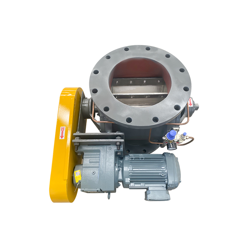
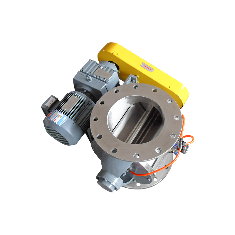
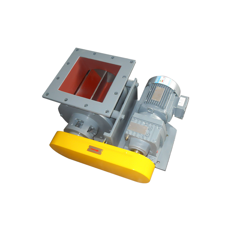
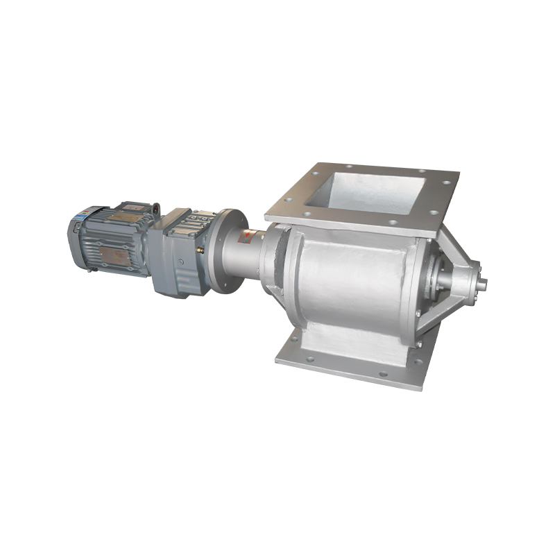
A rotary valve, also known as a rotary airlock valve or rotary feeder, is a mechanical device used to regulate the flow of bulk materials, such as powders, granules, or pellets, between two points in a pneumatic conveying system while maintaining a pressure or vacuum seal. Positioned at the base of hoppers, silos, cyclones, or dust collectors, rotary valves allow material to drop through in controlled increments without letting air escape or contaminants enter, which is critical for maintaining the pressure differential that pneumatic conveying systems rely on to move material efficiently.
When conveying systems experience problems like material buildup, inconsistent flow, excessive air loss, or premature equipment wear, the rotary valve is often at the center of the issue. Understanding how rotary valves work, the different types available, and how to match one to a specific application is key to resolving these conveying challenges and keeping a system running smoothly.
How Rotary Valves Work
At the core of a rotary valve is a rotor with multiple pockets or vanes that turns inside a close-tolerance housing. As the rotor spins, each pocket fills with material at the inlet, carries it around, and releases it at the outlet, while the tight clearance between the rotor tips and housing maintains an airlock that prevents pressurized air or vacuum from bypassing through the valve. This continuous, metered discharge allows the valve to both feed material into a conveying line and maintain the air seal needed for the system to function properly.
The rotor speed, typically controlled by a variable frequency drive, determines the rate of material discharge, making rotary valves useful not just for sealing but also for precise volumetric or gravimetric feeding in applications that require consistent material flow rates.
Common Types of Rotary Valves
Rotary valves come in several configurations, each suited to different material characteristics and system requirements.
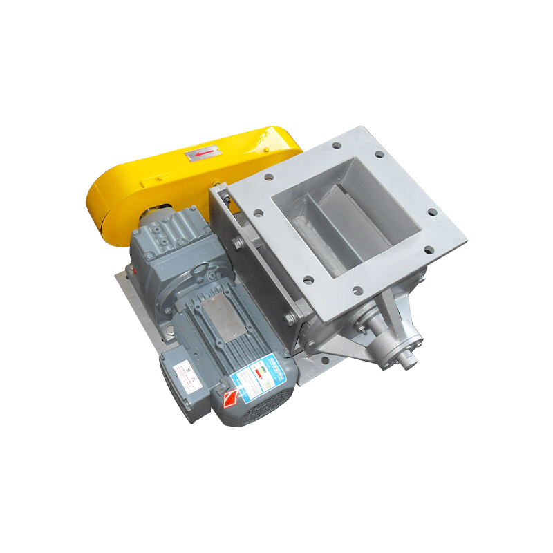
Drop-Through Rotary Valves
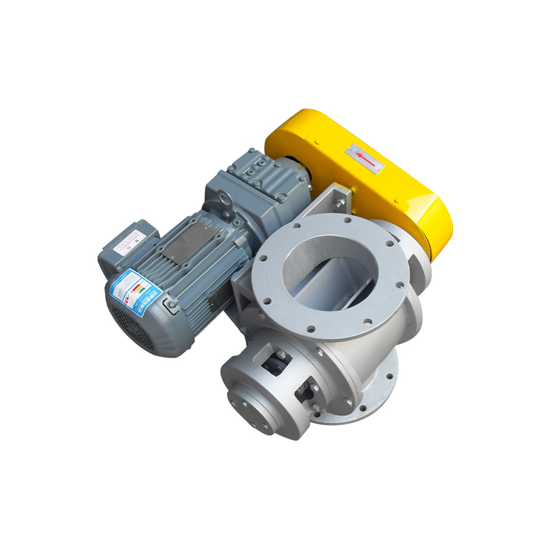
Drop-through valves are the most common type, with material entering from the top and exiting directly below through gravity as the rotor turns. They are simple, reliable, and well-suited for handling free-flowing powders and granules in low to moderate pressure applications.
Blow-Through Rotary Valves
Blow-through valves allow conveying air to pass directly through the rotor pockets, sweeping material out of the valve and into the conveying line. This design reduces material degradation and buildup, making it ideal for fragile, sticky, or fibrous materials that might otherwise clog a standard drop-through design.
Offset Rotary Valves
Offset valves feature a housing designed to reduce the shearing of material between the rotor and housing, making them a better fit for materials that are prone to degradation, such as friable pellets or granulated products that need to retain their shape during processing.
High-Pressure Rotary Valves
Designed with tighter tolerances and often additional sealing features like adjustable side plates, high-pressure rotary valves are built to handle pressure differentials beyond what standard valves can manage, making them suitable for dense-phase conveying systems operating at higher pressures.
Matching Rotary Valve Type to Material Characteristics
The physical properties of the material being conveyed play a major role in determining which rotary valve design will perform best and minimize wear or product loss.
| Material Type | Recommended Valve Type | Reason |
| Free-Flowing Powders | Drop-Through | Simple, cost-effective handling |
| Fragile Pellets | Offset or Blow-Through | Reduces shearing and breakage |
| Sticky or Fibrous Materials | Blow-Through | Prevents buildup and clogging |
| Abrasive Materials | Hardened Rotor/Housing Valve | Extends component wear life |
| Dense-Phase Conveying | High-Pressure Valve | Maintains seal at higher pressures |
Diagnosing Common Conveying Problems Linked to Rotary Valves
Many recurring conveying issues can be traced directly back to rotary valve performance or selection. Recognizing the symptoms helps operators identify whether the valve itself, its settings, or its wear condition is the root cause.
- Excessive air leakage: often caused by worn rotor tips or an incorrect valve size for the pressure differential
- Material bridging above the valve: can result from an inlet design mismatched to the material's flow characteristics
- Inconsistent feed rate: frequently linked to rotor speed control issues or uneven material density entering the valve
- Premature rotor wear: typically caused by abrasive materials paired with a standard, non-hardened rotor
- Material carryover or jamming: often the result of an oversized valve pocket relative to particle size
Addressing these issues usually starts with confirming the valve's specifications match current operating conditions, since process changes over time, such as switching material suppliers or increasing throughput, can shift requirements beyond what the original valve was designed to handle.
Sizing and Selection Considerations
Proper rotary valve sizing depends on several interconnected factors: the required material throughput, the bulk density of the material, the pressure differential across the valve, and the physical space available for installation. Undersized valves can create bottlenecks and increase wear from running at excessive speeds, while oversized valves may lead to poor sealing efficiency and unnecessary energy consumption.
Rotor pocket volume and speed together determine the valve's maximum throughput, so calculating the required feed rate against the rotor's displacement per revolution helps confirm whether a given valve model can meet production targets without exceeding recommended operating speeds, which typically range from 15 to 30 RPM for most standard applications.
Maintenance Practices That Prevent Conveying Downtime
Routine maintenance significantly extends rotary valve service life and prevents unplanned conveying system shutdowns. Regularly inspecting rotor tip clearances helps catch wear before it leads to significant air leakage, since even small increases in clearance can noticeably reduce sealing efficiency. Lubricating bearings and seals according to the manufacturer's recommended schedule prevents premature failure of moving components, which are often the first parts to wear out under continuous operation.
Periodically checking for material buildup inside the housing, particularly with sticky or moisture-sensitive materials, helps maintain consistent rotor movement and prevents jamming. For abrasive applications, tracking rotor wear patterns over time allows maintenance teams to plan rotor replacement proactively rather than reactively, minimizing the risk of an unexpected conveying line failure during production.